


Charge/Discharge System ControllerPFX2500 Series
- Power Tools
- Robot
- Electric Motorcycle
- Electric Vehicledrives
- The Power Conditioners for Stationery Power Storage
The test system enables you to carry out easily for the battery simulation of the actual environment. Comprehensive Management from Test Condition Setting, Execution and Test Result Analysis can be conducted by the Exclusive Application Software

Features
Energy Storage Essential to New Energy Application.
Fully support Charge and Discharge Measurement from Basic Test to Simulation Test
PFX2512/2532 Series is a high performance Charge/Discharge system controller that takes measurements in combination with our DC power supply and electronic load in order to evaluate test sample (electric storage elements such as secondary batteries) characteristics. It is also capable to perform evaluation test with high-performance, large capacity and wide range of rating with the combination of DC power supply and electronic load. Execution of the test is conducted by the exclusive application software. The test corresponds to long time continuous test and synchronization test with temperature chambers with the multiplexed protection performance. In addition, easy data editing is also capable with fulfilling graphic performance.

Complicated Systems Integrated into One
PFX2512/2532 Series has integrated systems into one unit where battery evaluation is required. In addition, the series has high degrees of flexibility corresponding to wide range of rating since it is possible to combine our conventional DC power supply (for charging) and our electronic load (for discharging) tailored to needs. Introduction cost is able to be reduced by selecting equipment which meets charge/discharge test condition required.

Easy Configuration
It is possible to configure the system by yourself. The DC power supply and electronic load that are applied configuration with PFX2512/2532, can be used for the system. This allows you to have a test system at low cost.
Control of the Constant Current (CC) and Constant Voltage (CV)
The adoption of the digital CC/CV control method minimizes the disparities in the constant current(CC)/ constant voltage(CV) setting accuracy and drift characteristics due to the differences in the system component devices(DC power supplies and electronic loads). This ensures highly accurate tests. There is absolutely no need to make adjustments after system configuration.
Highly accurate measurement
Highly accurate measurement circuits are built in. Battery voltage and charge/discharge current are detected with high accuracy. (Voltage measurement: 100 μV resolution, current measurement: 100 μA resolution, elapsed time measurement: monthly error of 30 s or less (10 ppm or less)) True electric energy and integrated capacity can be measured even for pulse currents that are difficult to be captured.
Protection Functions for Safety Operation
Equipped with protection functions provided by hardware and software against phenomena such as overcharge and overdischarge. The route switch (load switch) is built in the PFX2500 series and it equips with a function to ensure connection between the DUT (batteries) and the DC power supply/electronic load as well as a high-speed interruption function that promptly disconnects the DC power supply/electronic load in case any abnormal state is detected. In addition, the vibration sensor detects major vibration and shock in case of a disaster or accident during charge and discharge test, then shuts off the output, and it prevents a damage to the connected equipment and the DUT (batteries).
Up to 10000 Steps for Pattern Charge/Discharge
It is capable to set the CC/CP (with V, I limit) step values up to 10000. Complicated charge/discharge test with minimum 100 ms step of time window since high speed charge/discharge transfer control becomes functional. This widely corresponds to the generation of test patterns or simulation patterns for various specification tests.
Capable of Expanding Measurement Function
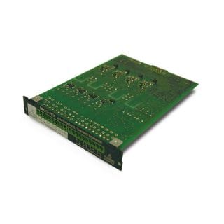
Measurement points, 4 points for voltage and 4 points for temperature, are able to be added by installing optional voltage/temperature Unit, OP02-PFX. Since there are 3 slots for optional board, measurement point addition is capable up to 12 points for voltage and 12 points for temperature as
maximum.
By installing an Voltmeter Unit OP03-PFX in an option slot on the SL01-PFX*1, you can increase the number of voltmeter measurement points. If OP03-PFX units are installed in all option slots of the SL01-PFX*1, voltage measurement points can be expanded to 64 points.
*1 OP02-PFX cannot be installed. When using the option “SD01-PFX”, one of the internal expansion slot of PFX2353/2512 will
be used.
Descriptions of Charge/Discharge Test
With the PFX2512/2532, various electrical characteristic tests are able to be performed regardless battery manufacturer or customers.
I-V Characteristics Test / Cycle Characteristics Test / Charge/Discharge Rate Test / Temperature Characteristics Test / Charge/Discharge Efficiency Test / Capacitance Measurement Test / Storage Characteristics Test / Capacitance Change Test / Capacitance Change Test / BMS Validation Test
Corresponding to Specification Test Pattern by Realizing Seamless Charge/Discharge
A certain time was required for transferring power supply and electronic load in the past. Seamless charge/discharge transfer has been realized at PFX2512/2532 by the simultaneous control of power supply and electronic load. For this reason, correspondence to characteristic test of recapturing complex applications such as application where charge/discharge repeating without taking breath is performed for electric motorcycle and electric assisted bicycle as well as electric vehicle and hybrid vehicle, and application for UPS for peak shift and to specification test pattern where continuous charge/discharge is performed such as IEC62660 became possible.

| 2 values CC pattern charge/discharge | |
|---|---|
| Step 1 | CHG: 200 A 500 ms |
| Step 2 | DISCH: –200 A 500 ms |

Realized Maximum 1 ms High Speed Data Sampling
Minimum 1 ms (maximum 6000 points for every profile) voltage/current measurements are capable by assigned voltage and current steps as trigger. This is most suited to impedance analysis of test and evaluation of life determination since high-precision voltage waveform synchronized to step current can be acquired.
- Sampling rate: selected from 1 ms/10 ms/100 ms
- Cell voltage meter: fixed at 100 ms of sampling rate (at OP02-PFX installed)
- 4 types of measurement start triggering (just after charge- discharge start/just before charge-discharge completion)
- 6000 sampling storage: 6 s @1 ms/60 s @10 ms/ 600 s @100 ms

More Accurate Single Cell Evaluation with 6V Range
PFX2512/2532 equips Voltage Range transfer capability between 6 V and 60 V. A 6 V range was newly installed in PFX2512/2532 in order to perform evaluation more accurately even for a single cell. 6 V range accuracy = ±(0.05 % of reading + 0.04 % of rating), 60 V range accuracy = ±(0.05 % of reading + 0.02 % of rating). In addition to the stacked cell assembly, more accurate characteristic test is capable with single cell.
Applied to CAN interface
PFX2512/2532 (BPChecker3000) is able to communicate with exclusive application where communication log, analysis, emulation functions, etc, are added. Herewith, it becomes possible corresponding to various demands such as synchronization between charge/discharge control and log segment, charge/discharge control from exclusive application. For details, please refer to page 6 and 7.
Rear Panel (PFX2512)

Rear Panel (PFX2532)

System Configuration
2532 System Configuration example


Personal computer: Windows 7 or Windows 8. Display resolution: 1280 × 1024 or more Equipped with 10 Base T(or higher model) LAN interface.
Thermostatic chamber: Supports synchronized operation with temperature chambers. To perform synchronized operation, temperature chambers equipped with a communication function, manufactured by ESPEC and the associated components are required. For details, please consult with us.
2512 System Configuration example


Personal computer: Windows 7 or Windows 8. Display resolution: 1280 × 1024 or more Equipped with 10 Base T(or higher model) LAN interface.
Thermostatic chamber: Supports synchronized operation with temperature chambers. To perform synchronized operation, temperature chambers equipped with a communication function, manufactured by ESPEC and the associated components are required. For details, please consult with us.
Specifications
Outline specifications
Rated output
| PFX2512 | PFX2532 | ||
|---|---|---|---|
| Number of outputs | 1 ch | 1 ch | |
| Charging current range*1 | 0.000 A to 50.000 A | 0.000 A to 200.000 A | |
| Charging voltage range*1 | 60 V range | 0.000 V to 60.000 V | 0.000 V to 60.000 V |
| 6 V range | 0.000 V to 6.000 V | 0.000 V to 6.000 V | |
| Discharge current range*1 | 0.000 A to 50.000 A | 0.000 A to 200.000 A | |
| Discharge voltage range*1*2 | 60 V range | 0.000 V to 60.000 V | 0.000 V to 60.000 V |
| 6 V range | 0.000 V to 6.000 V | 0.000 V to 6.000 V | |
Measurement accuracy
| PFX2512 | PFX2532 | |||
|---|---|---|---|---|
| Static | ||||
| Charge/ discharge Current measurement | Range | 0.0000 A to 50.0000 A | 0.000 A to 200.000 A | |
| Accuracy*3 | ± (0.15 % of reading + 0.02 % of rating) | ± (0.2 % of reading + 0.1 % of rating) | ||
| Resolution | 0.1mA | 1mA | ||
| Voltage measurement | Range | 60 V range | -6.0000 V to 60.0000 V | -6.0000 V to 60.0000 V |
| 6 V range | -1.0000 V to 6.0000 V | -1.0000 V to 6.0000 V | ||
| Accuracy*3 | 60 V range | ± (0.05 % of reading + 0.02 % of rating) | ± (0.05 % of reading + 0.02 % of rating) | |
| 6 V range | ± (0.05 % of reading + 0.04 % of rating) | ± (0.05 % of reading + 0.04 % of rating) | ||
| Resolution*4 | 0.1mV | 0.1mV | ||
| Power measurement | Range | 0.000 W to 3000.000 W | 0.0 W to 12000.0 W | |
| Accuracy | Software calculation (voltage measurement × current measurement) | |||
| Resolution | 1mW | 100mW | ||
| Current Capacity calculation | Range | 0.000 Ah to 2000.000 Ah | 0.000 Ah to 2000.000 Ah | |
| Accuracy | Depends on the current measurement accuracy and the time accuracy | |||
| Resolution | 1mAh | 1mAh | ||
| Time*5 | Accuracy*3*6 | ±10 ppm (TYP values) | ±10 ppm (TYP values) | |
*1 Range might be different depending on power supply to be connected, model of electronic load, wiring situation, etc. *2 Lowest dischargeable voltage might be different depending on electronic load model to be connected, wiring situation, etc. *3 Ambient temperature at 18 °C to 28 °C *4 Common with 6 V/60 V ranges *5 Accuracy of transit times (termination condition) at charge/discharge time and at rest. *6 Corresponding to 30 seconds of monthly difference.
PFX2500 series specification comparison
| Item | PFX2512 | PFX2532 |
|---|---|---|
| Rating | 60 V / 50 A | 60 V / 200 A |
| Communication interface | LAN | LAN |
| Monitoring data minimum time interval | 0.1 s | 0.1 s |
| High speed data sampling*4 | ✔︎ (Selected form 1 ms/10 ms/ 100 ms maximum 6000 points for every profile) | |
| Charge/discharge mode | 9 modes Charging: CC, CC-CV(Cell CV Voltage)*1 Discharging: CC, CP,CC-CV(Cell CV Voltage)*1, CP-CV(Cell CV Voltage)*1 Others: Pattern(CC, CP, Cell CV voltage*2), I-V, Pause | |
| Test condition configuration | Individual Profile Setting (unlimited) for Charging/Discharging, etc Conditional branching function from charge/discharge results is available. | |
| Seamless charge/discharge | ✔︎ (Response within 50 ms (TYP)*3) | |
| Rest time control | The time variable by cell temperature | |
*1 Can be set only when the optional OP02-PFX Volt/Thermometer Unit or OP03-PFX Voltmeter Unit is installed. *2 Can be set only when the optional OP02-PFX Volt/Thermometer Unit or OP03-PFX Voltmeter Unit is installed. Step time can be used in more than 500 ms. *3 It is defined as the time for the charge/discharge current to change from 10 % to 90 % of the preset value (ratedvalue). *4 The main body voltmeter/ammeter is applicable. (Cell voltmeters are not supported.)
Line-up
*SD007-PFX is mandatory for operation of PFX2512 and 2532.
The System with PFX2500 Series
Applied configuration (model ID)
Model ID is used for combination of the selected power supply and electronic load if you wish to have a combination that is not on the available model ID list, please consult with us.
| Model ID | Power supply for charge | Electronic load for discharge |
|---|---|---|
| PFX2512 | ||
| 7103 | PWR1600L | PLZ1004W(2 units in parallel)*2 |
| 7105*4 | PAT60-67T | PLZ1004W+2000WB*1 |
| 7106 | PWR1600L | PLZ1004W*2 |
| 7107 | PAS10-70 | PLZ1004W*2 |
| 7110 | PAS40-27 | PLZ1004W*2 |
| 7112 | PAS10-35 | PLZ334W*2 |
| 7119 | PWR1600L | PLZ1004W+2000WB*1 |
| PAS60-12 | PLZ1004W*2 | |
| PWR1600L | PLZ664WA*2 | |
| 7122 | PAS60-12 | PLZ664WA*2 |
| 7124 | PAS40-9 | PLZ1004W*2 |
| 7125 | PWR1600L | PLZ664WA*2 |
| 7126 | PWR801L | PLZ1004W*2 |
| 7127 | PWR801ML | PLZ1004W*2 |
| 7128 | PWR1201L | PLZ1004W*2 |
| 7151 | PWR401L | PLZ205W*2 |
| 7152 | PWR401ML | PLZ205W*2 |
| 7153 | PWR401L | PLZ405W*2 |
| 7154 | PWR401ML | PLZ405W*2 |
| 7155 | PWR801L | PLZ1205W*2 |
| 7156 | PWR801ML | PLZ1205W*2 |
| 7157 | PWR1201L | PLZ1205W*2 |
| 7158 | PWR1201ML | PLZ1205W*2 |
| 7159 | PWR1201ML | PLZ1205W(2 units in parallel)*2 |
| 7160 | PWR1201ML | PLZ1205W+2405WB*1 |
| Model ID | Power supply for charge | Electronic load for discharge |
|---|---|---|
| PFX2532 | ||
| 7301 | PWR1600L (2 units in parallel) | PLZ1004W*2 +2004WB |
| 7302 | PAT60-133T | PLZ1004W*2 +2004WB x 2 (2 units in parallel)*3 |
| 7303 | PAT40-200T | PLZ1004W*2 +2004WB x 2 (2 units in parallel)*3 |
| 7304 | PAT40-200T | PLZ1004W*2 +2004WB |
| 7305 | PWR1600L | PLZ1004W*2 |
| 7306 | PAT40-200T | PLZ1004W*2 |
| 7307 | PWR1600L | PLZ1004W*2 x 2 (2 units in parallel) |
| 7351 | PWR1201L | PLZ1205W*2 |
| 7352 | PWR1201L | PLZ1205W(2 units in parallel)*2 |
| 7353 | PAT60-133T | PLZ1205W*2 +2405WB x 2 |
| 7354 | PAT40-200T | PLZ1205W*2 |
| 7355 | PAT40-200T | PLZ1205W*2 +2405WB |
| 7356 | PAT40-200T | PLZ1205W*2 +2405WB x 2 |
| 7357 | PAT40-200T | PLZ1205W*2 +2405WB x 3 |
| 7358 | PAT40-200T | PLZ1205W*1 +2405WB x 4 |
| 7359 | PAT80-100T | PLZ1205W*1 +2405WB x 4 |
*1 M range *2 H range *3 Can be replaced with the Kikusui SR Large Capacity Electronic Load Smart Rack System PLZ5004W. *4 A separate cable is required. For details, contact your Kikusui agent or distributor.
* A SC07-PFX (optional) is necessary to connect the PWR-01 series with the PFX2500 series.
* A SC05-PFX (optional) is necessary to connect the PLZ-5W series with the PFX2500 series.
Note on selecting power supply for charge (route loss)
Application of the charge current causes a voltage drop in the DUT cable, connecting cables, the current pass route of the PFX2500 series, etc. The power loss at charging caused by this voltage drop is the route loss. The maximum power that can be used for charging is the value from which the route loss is subtracted.
[Maximum charging power = maximum rated power of DC power supply – path losses].
Note on selecting electronic load for discharge (minimum operating voltage for discharge)
The electronic load has minimum operating voltage (1.5 V in PLZ1004W), and it does not operate
at the voltage below the specified level. The result of an addition of this level and the route loss
(voltage drop) is the minimum operating voltage for discharge.
[Minimum operating voltage for discharge = Minimum operating voltage of electronic load + Voltage
drop caused by route loss]
Conceptual diagram of path loss

Options
Series options. For more information on optional products, please refer to the individual product pages.


